FATRAT (v2) is a
development following on from the design of FATRAT which used a very expensive
(US$1000) CPU board from Diamond Systems which had an ADC on-board. The FATRAT system used a Linux operating system and
had good support from Diamond Systems for board control/software.
FATRAT was a 10-channel
system and was expected to cost at least US$120 per channel for components
inside box – hence excluding cables/geophones.
FATRAT also was based on 12V sealed
lead-acid batteries as opposed to FATRAT (v2) which uses a 7.4V Li-ION battery.
FATRAT (v2) has been based
on the ARDUINO boards popular among electronics hobbyists. ARDUINO has massive user support and their
products now have some sophisticated versions.
A company based in
USA, Adafruit, has a wide range of ARDUINO products and great support in terms
of product documentation and software libraries.
FATRAT2 uses the
following Adafruit boards
- Grand
Central Metro M4, 120Mhz CPU, 3.3V, onboard SD card
- Metro M0
express, 48Mhz CPU, 3.3V
- Ultimate
GPS Featherwing, 3.3V, on-board button battery backup
And from Seeeduino,
another ARDUINO manufacturer
- HP20C High
resolution Barometer.
It was deemed
expedient to use 2 x CPU on FATRAT (v2) to easily separate operational
functions.
1) The Metro
M4 does the main data acquisition on 8 seismic channels and 4 AUX channels at a
sample rate of 1 millisecond. It would
handle either more seismic channels (10 would be maximum) or higher sampling
rate, 0.5 msec if required. It writes
the data to SD card in 1 hour long type data files.
2) The Metro
M0 receives the SERIAL NMEA messages from the GPS unit, parses them into a
SUPER NMEA message and creates a “sort of analog-based serial string” and
outputs these values on the Metro M0 Digital to Analog Converter (DAC) which is
connected to one of the Metro M4 AUX channels.
Block diagram overviews
of the Metro M4 and Metro M0 are below

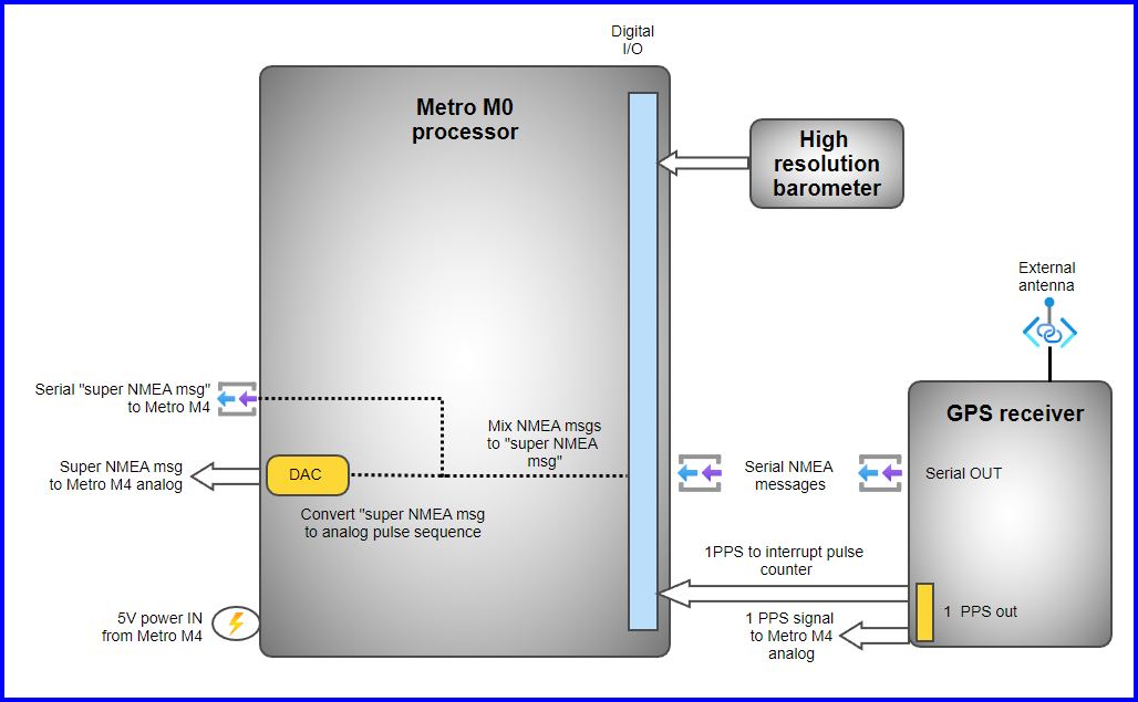
The main function of
this device is to listen to the GPS unit and parse the various NMEA strings
into a single “super message” which has all the parameters required to get date/time/position/satellite
integrity. The readings of barometric
pressure, barometric height and temperature are also added to the end of the
“super message”.
The GPS receiver has
been configured to output NMEA strings every 3 seconds rather than the default
of 1 second.
So every 3 seconds a
group of NMEA strings are received and then parsed into a large NMEA message to
which are added the barometric data to form a “super message” of some 120
characters. The M0 processor then
creates digital values to feed to the DAC to convert the 120 character string
to an analog output pulse sequence.
The
style of this pulse sequence is shown below showing output fed to the M4
processor.

At the start of the pulse
sequence is a “Leading pulse” with a value of the maximum of the DAC, 12 bits =
4095. This is followed by a STAIRCASE of
10 values which represent the values 0 through 9. These values are some 15% lower in amplitude
than the “Leading pulse” to distinguish them.
This adds a level of integrity to each character type sequence in that we
have values for each digit to read the following digits.
A “Trailing pulse” of
value 4095 is also at the end of the sequence.
Each character in the
string is converted to its ASCII value and then has a value of 32 subtracted
from its value (which is the value of the ASCII <SPACE> character). Since we want a character to be represented
by ONLY 2 digits, we have a range of values from 0 to 99. Adding 32 means ASCII characters from
<SPACE> at 32 to ASCII 134. Hence
we include ALL UPPER and LOWER case alphabetic characters, digits 0-9, plus
various brackets and other unusual characters.
The value 99 is used
to be an ILLEGAL value i.e. a bad character in the “super message” due to NMEA
corruption maybe. Values 0 to 98 are
valid characters.
This channel of data
being fed to the M4 processor can be considered the “information channel”.
A complete “super message” is shown below with
1000 samples per strip across
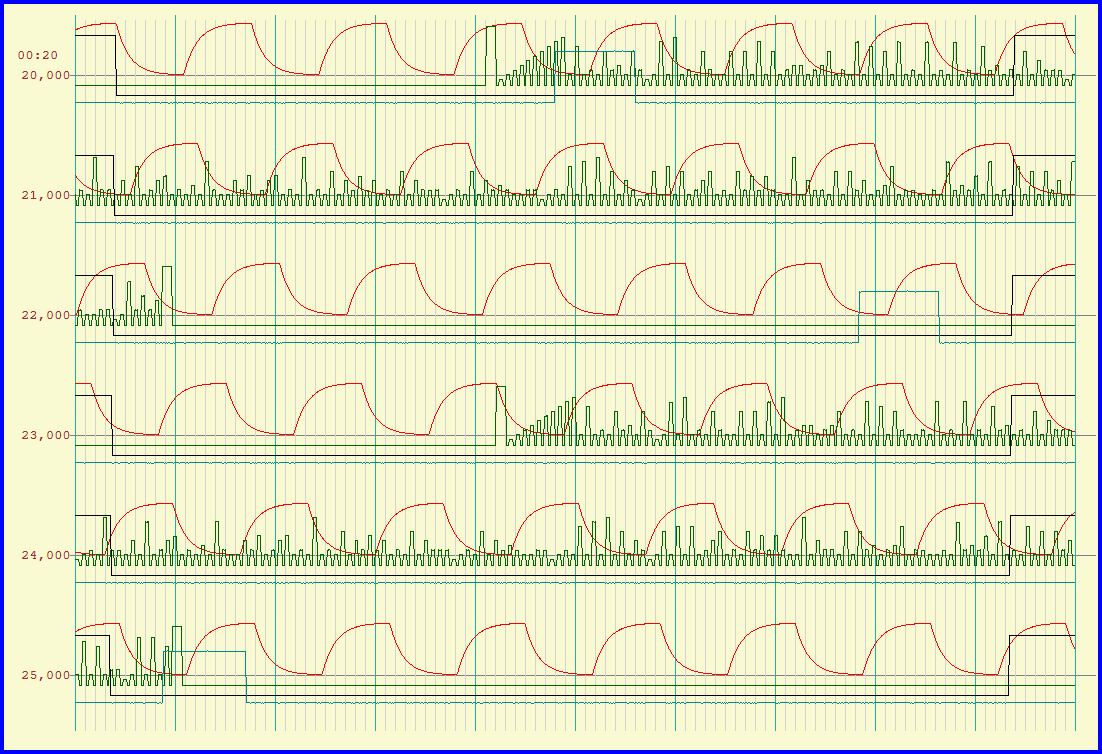
This image shows 2
complete “super message” strings as analog pulses of just under 2 seconds long. It can be considered a “sort of” very slow
SERIAL string.
The pulses for each
character are 2 x decimal values and each pulse is set at 4 msec wide with a
gap of 3 msec between, so each ASCII character takes 7 msec. The “leading”, “trailing” and “staircase”
values would add about 100 msec to sequence.
The M4 processor is
the main processor of the FATRAT2 module.
It is basically a datalogger that continuously records seismic data
channels and 4 x Auxiliary channels which include the 1PPS signal plus the M0
DAC super message as an analog pulse sequence.
The M4 processor has
been setup to have 3 operating modes
1. STANDBY 2. GPS Monitoring 3. DATA LOGGER
Each of these modes is
initiated by a dedicated BUTTON on the FATRAT2 module. Holding the button for 2 seconds enters the
appropriate mode.
STANDBY
At power-Up the M4
enters STANDBY mode which simply monitors the battery voltage and waits
to receive commands over the Bluetooth connection. Commands can be used to read the EEPROM
memory (like a small disc drive) of the M4 or conversely to enter information
such as Client name, Area, Geophone configuration, field PEG number (field physical
location of FATRAT2) into memory.
GPS MONITORING
In the second mode, GPS
Monitoring, the M4 processor reads a SERIAL version of the “super NMEA
message” from the M0 board. This serial
port is NOT listened to during any data logging operation as a single analog
AUX channel records this information as described in M0 description.
This GPS Monitoringmode gives the field operator FULL information as to the accuracy and
integrity of the GPS data and confirms that the 1PPS pulse is being received
properly. This mode would ensure that
everything is OK before turning on the Data Logging mode.
DATA LOGGING
The final third mode
is Data Logging mode. This mode
simply loops whilst acquiring data samples at a rate of 1 millisecond on all 12
channels, 8 seismic and 4 auxiliary and uses a double buffering system to enable
data to be written to SD card from 1 buffer whilst data is being stored in
second buffer. Data files are organized
as ONE hour files with a simple naming convention
YYMMDDHH.XXY (a DOS based 8.3 file naming convention for simplicity)
YY = year MM =
month DD = day of month HH = hour of day (based on UTC hour)
XX = 2 hexadecimal box
identification code Y = alphanumeric
indicator of the file within the hour
Y would normally just
be “A” but if user switches modes a few times then the code increments to “B”
then “C” etc enabling a maximum of 26 “interruptions” per hour. One expects that only 1 or 2 codes would ever
be needed.
The system uses a real
time clock (RTC) to monitor the time and this is synched with GPS every few
hours. The RTC has proved to be within
seconds even after a few weeks.
Just before the hour
changes, say 20 seconds before, the current files is closed, several counters
etc reset and then a new hourly file generated.
During this 20 second period no data is therefore recorded so for a perfect
field operation the energy source would not operate during this time as well. This is easy to achieve as the energy source
timebreaks are being recorded by a FATRAT module as well hence energy source
operator can be warned to pause operations at that time.
Duty
cycle graph for writing to SD card whilst using 16 channels (maximum) is below. It only uses about a 20% duty cycle but there
are occasional latency jumps which can increase this to say 30-40% but usually
very infrequent.

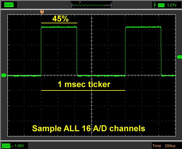
A
similar graph for the duty cycle of the ADC during the 1 msec sampling is below
showing some 45% duty cycle when sampling ALL 16 channels, 12 channels is
proportionately less.